|
|
|||||||
|
David Della Rocca website English version by Bert Vrusch website |
|
Size:
441 ko
Platform: Mac/PC |
|
infos: |
| Animating a vehicle - Part 2 |
| This tutorial will explain how to achieve a car that follows a terrain surface, and how to accomplish the car body to auto orientate itself, while watching the wheels' height. | ||
 |
Importing the models - Import your terrain - Scale it to the desired size and place it slightly underneath your vehicle - Export it while going into the "Object" menu -> Export Parked Fact Object You have to reset all scale, position and rotation values to 0.0 - This action is useless if your terrain is already at the right position after import. - Export it while going into the "Object" menu -> Export Parked Fact Object - Import the new terrain model again - Import your vehicle at starting position, slightly above the terrain surface and aligned to the Z axis. |
|
Step 1 - Attaching the vehicle to ground level - Create 4 null objects and place them in the centre, but inside each wheel - Rename them into "wheel fix 1", "wheel fix 2", "wheel fix 3" and "wheel fix 4" Now we will use 4 cubes at the size of each wheel, that will help them to be glued to the terrain. - In the Plugin menu, choose Uber Shape EIU.plm - Choose a cube shape - Enter the size of a wheel. In this example we use : x: 22 y:66 z:66 - Uncheck "Auto-name" and click OK - Export it while going into the menu Object -> Export Parked Fact Object - Import the cube again - Place it's axis at the bottom (Open the Joint Editor, click on the X-form Tab and choose "Bottom" for Link alignment Position) - Duplicate this one three times and place each copy at the exact position of your real wheels |
 |
|
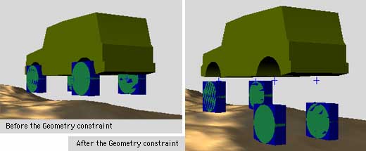
- Rename them as "wheel contact 1", "wheel contact 2", "wheel contact 3" et "wheel contact 4" - Group each wheel (wheel 1, 2, 3, 4) as children under wheel contact 1, 2, 3, 4 - Then group wheel contact 1, 2, 3, 4 as children under wheel fix 1, 2, 3, 4 Now we're finally ready. We will now apply the "Geometry" constraint on the four cubes "wheel contact". This constraint will force the cubes to follow the geometry, meaning the shape of our terrain, and since the wheels are grouped underneath, they will do the same. - Select the 4 "wheel contacts" - In the Constraint menu, choose Geometry - Click OK when the first alert message appears - Then click on the terrain. Normally you should now see the four cubes and wheels position themselves on top of the terrain. |
 |
|
 |
||
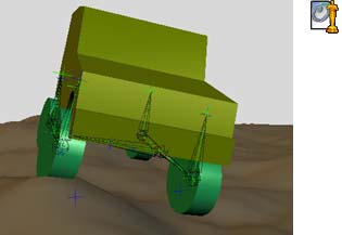
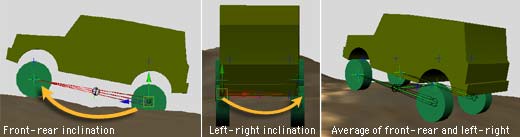
| - Open the Constraint Editor window of "wheel contact 1" - Uncheck position X and Z, leaving only position Y activated. In this way the wheels will only follow the terrain regarding the Y axis, sort of gliding on a tube or a shock absorber. As you can see, our tyres are now glued to the asphalt :-)) And if we just could move this a bit ... Step 2 - Animating the car - Create a null object and place it at the centre of the rear axle - Rename it as "Car mover" - In the Constraint menu, choose Auto Bank and apply the constraint to itself - Open the "Car mover's" Constraint editor window - Click on Car Mover in the list and change the Weight value into 0.0 - Uncheck "Enable Auto Roll" - Finally, group the 4 "wheel fix" null objects as children under "Car mover" - In the project window, uncheck the 4 cubes called "wheel contact", since we don't need them to be visible. That's a good start, right ? But now we have to make sure that our car body follows these movements as well. To achieve this, I will offer you a relatively simple but efficient solution. Our goal is to accomplish that the car body interpolates it's rotation, depending on the position of each of the 4 wheels. Step 3 - Alignment of the car body at the wheels - In the top view window, create a bone that stretches from the rear left wheel to the front left wheel - Rename it as "Bone L" (Animator will add a null object at the end called Joint End, just leave it there) |
||
| - Duplicate this bone and reposition it at the level of the right wheels, rename it as "Bone R" - Create a third bone, that stretches from the middle of Bone L to the middle of Bone R - Rename this one as "Bone Roll Z" - Group this one as a child under Bone L (with it's Joint End) - Select "Bone L" and it's Joint End - Go into the Character menu and select Add IK Handle - Rename this IK Handle as "IK Handle L" - Select "Bone R" and it's Joint End - Go into the Character menu and select Add IK Handle - Rename this IK Handle as "IK Handle R" - Duplicate the Joint End that is grouped under "Bone Roll Z" - Group this Joint End copy as a child under "Bone R" , and rename this one as "Joint End Roll Z" - Select "Bone Roll Z" and his Joint End - Go into the Character menu and select Add IK Handle - Rename this IK Handle as "IK Handle Roll Z" - Group this one as a child under "Bone R" Now, don't get too depressed, we're almost there :-) - Create a final null object and place it at the centre of "Bone Roll Z" - Rename it as "car fixation" and group it as a child under "Bone Roll Z" - Group the car body (Car) as a child under "car fixation" |
 |
|
The final straight line...here's where all the magic comes together - Select "Bone L" - In the Constraint menu, choose Position and assign "wheel contact 1" (rear left wheel) as a target. - Select "Bone R" - In the Constraint menu, choose Position and assign "wheel contact 2" (rear right wheel) as a target. - Select "IK Handle L" - In the Constraint menu, choose Position and assign "wheel contact 3" (front left wheel) as a target. - Select "IK Handle R" - In the Constraint menu, choose Position and assign "wheel contact 4" (front right wheel) as a target. If you carefully followed these steps, you should now see the car body align and orientate itself at the 4 wheels. |
||
 |
||
Step 4 - Orientating the wheels There's one remaining issue to take care of, but it's totally up to you to decide if this is really a necessity in your animation. If you really look closely, you will see that the 4 wheels remain impeccably straight, unregarding the terrain's inclination. A simple solution to change this annoying behaviour, would be to activate "Use surface normals" in the Geometry's constraint...however if you would do so, each wheel would independently be influenced by the terrain's inclination, resulting in four different directions when engaging every single bump. Therefor, we will use a different method to make the 4 wheels incline in relation to the car's body. |
||
| - Create a bone that stretches from the front wheel up to the car body, exactly like you would see in a shock absorber. - Rename it as "wheel Roll Z" , with the corresponding wheel numbers (1, 2, 3, 4) - Duplicate it and position one of these at every wheel - Add corresponding numbers to each of them (1, 2, 3, and 4) - Select both "wheel Roll Z1" and it's Joint End - Go to the Character menu and select "Add IK Handle" - Repeat this operation for the other 3 bones. Right now we have 4 IK Handles on top of our 4 bones. Those IK Handles are taking care of controlling the bones' orientation, if you translate one of them, the bone will incline to follow it. - Group these 4 IK Handles as children under "car fixation", the null object on which the car body is fixed. |
 |
|
| - Group "wheel Roll Z1" as a child under "wheel contact 1" - Next, group wheel 1 as a child under "wheel Roll Z1" instead of "wheel contact 1" Do the same thing for the other 3 wheels. As you can notice, watching the right part of this page, the final hierarchy has become a little complex...but after a couple of tryouts, you will see that it was worth the effort. Allright, we've reached the end of this second episode, until next time and ...ciao!!! David |
||
| Special hint : - You can use all of these recepies and apply them to any kind of vehicle, cars with 3 wheels (ATC), trucks driving on 10 wheels or whatever imaginable vehicle, so let's not limit ourselves, but experiment ! - The geometry constraint does not allow using multiple objects as targets, for instance a road and a sidewalk, or a terrain and a rock, which can be frustrating sometimes. As a workaround to this limitation, duplicate all objects that need to serve as targets and group them under the "Dicer" plugin. Within Dicer, change the "Segment count" value to 1. Export the Dicer plugin as FACT object, while using the option "selected only". Next, import the model again that you've just created. All these pieces are now welded together and represent a single object. All that remains to be done, is assigning the object as a target and turning it invisible in the project window. In this way, your vehicle will roll on both sidewalks and rocks as well. |
 |
|
|
|